
Common problems, causes and solutions of die casting mould
Author: SAIVS Date Published: Nov 08,2024
Common Issues:
Ejector pin jams or breaks
Pointed position of the ejector pin
Material build-up at the ejector pin site
Deep or excessive projection of ejector pin marks on product surfaces
Root Causes:
Insufficient or rough internal diameters of ejector pin holes, overly tight assemblies.
Excessive sealing depth or lack of clearance in the ejector pin holes.
Oversized or irregularly shaped ejector pin holes leading to loose assembly.
Inadequate maintenance during production, grease build-up, or lack of lubrication.
Mold closure prior to ejector pin retraction or proper part ejection, damaging pins.
Inconsistent pin positioning due to improper countersinking.
Incorrect installation due to unmarked pin and plate alignment.
Misalignment of garbage pin on ejector plate.
Weak or thin ejector plate, lacking reinforcement, leading to deformation.
Substandard material quality or heat resistance of the ejector pin.
Wear in pin hole due to poor-quality core material.
Use of undersized ejector pins.
Solutions:
Maintain hole clearance for smooth ejection, targeting a tolerance of 0.015mm per side (e.g., for a Φ6mm pin, set the hole to Φ6mm+0.03/0).
Limit sealing depth to 25-30mm; avoid voids in core areas.
Keep the ejector pin slightly elevated (0-0.05mm above core surface).
Use heat-resistant, standardized pins for smaller diameters (<3mm).
Prioritize regular maintenance of ejector components.
Shut down production promptly when abnormal conditions arise.
Handle ejector replacement carefully to avoid core damage; if stuck, use appropriate release techniques.
Ensure correct assembly and verify positioning.
")
2. Core Pin/Insert Issues
Common Issues:
Broken, bent, or worn core pins/inserts
Crushing of core pins/inserts
Root Causes:
Poor material selection, incorrect hardness, or exceeded service life.
Insufficient Draft Angle or excessive pin/insert length.
Lack of clearance at contact points.
Improper use of release agents during production.
Mold closure before complete retraction, damaging pins/inserts.
Misuse of ejector pins to release stuck inserts.
Inappropriate cleaning techniques, such as hydrochloric acid.
Solutions:
Use High-quality materials, aim for surface hardness of HRC48-52, or apply nitriding/titanium plating.
Maintain a draft angle of ≥1° for rear molds (≥1.5° for front molds); chamfer ends of pins/inserts.
Ensure clearance of 0.05-0.10mm at contact points.
Maintain pins/inserts properly during production.
Halt production promptly if issues arise.
Avoid forceful removal; seek specialized methods if necessary.
Prohibit acid cleaning.
3. Mold Core Issues
Common Issues:
Surface irregularities and burning on mold cavity
Erosion, corrosion, cracking, and deformation
Oil leakage from mold core
Root Causes:
Inadequate finishing of mold cavity surface.
Improper material or heat treatment selection, resulting in suboptimal hardness.
Core material exceeding service limits.
Uneven application of release agents during production.
Poor maintenance practices, leading to debris accumulation.
Mold closure before full part ejection, causing damage.
Incorrect cleaning methods, such as acid soaking.
Solutions:
Maintain consistent finish on cavity surfaces.
Use high-grade core materials with surface hardness of HRC46-50, or apply nitriding/titanium plating.
Temper mold core at regular intervals, e.g., after 10,000 cycles.
Maintain clean cavity surfaces, free of debris and foreign matter.
Halt production when issues occur.
Avoid acid use on core surfaces.
Verify smooth oil flow and tight connections post-assembly.
4. Sprue Sleeve/Splitter Cone Issues
Common Issues:
Damaged gate bushing and nozzle fit
Nozzle sticking, flaring, or leakage
Root Causes:
Inadequate material or heat treatment, resulting in insufficient hardness.
Poor finishing on internal surfaces.
Excessive clearance, poor mold fitting.
Oversized or improperly sized bushing holes.
Worn cooling circuit threads, loose fittings.
Solutions:
Use high-quality materials with surface hardness of HRC48-52, or apply nitriding/titanium plating.
Ensure high-quality finishes on bushing surfaces.
Verify clearance and dimensions during assembly.
Maintain clean and well-aligned bushing components.
Verify tight connections and oil flow prior to production.
5. Slider/Row Position Issues
Common Issues:
Stuck sliding blocks, damaged row positions, water erosion
Root Causes:
Inadequate strength or wear resistance in die wedge.
Insufficient sealing width on slider causing deformation.
Poor fit between sliding block and guide surfaces.
Insufficient T-slot dimensions.
Unbalanced guide pillar strength.
Solutions:
Reinforce die wedge strength, add hardening blocks.
Ensure ample slider dimensions and sealing width.
Confirm proper fit between sliding block and guide surfaces.
Maintain T-slot dimensions, use strong pressure bars.
Follow precise alignment and assembly protocols.
6. Oil Cylinder Issues
Common Issues:
Oil leakage at seal points
Root Causes:
Insufficient heat resistance in oil cylinder, causing seal damage.
Improper oil pipe connections.
Solutions:
Use high-temperature-resistant oil cylinders, rated for extended use.
Replace seals with heat-resistant alternatives as needed.
Regularly inspect and reinforce oil pipe connections.
7. Exhaust Plate Issues
Common Issues:
Excessive flashing, magnesium carbide build-up, plate collapse
Root Causes:
Poor fit between exhaust plates and formworks.
Inadequate alignment and stabilization of exhaust plate.
Debris accumulation due to inadequate maintenance.
Solutions:
Ensure a precise fit between exhaust plate and mold during production.
Regularly clean and maintain exhaust plates to prevent debris build-up.
Shut down production when abnormalities are detected.
Why Choose SAIVS™ as Your Supplier?
1.Superb Quality Control Management
At SAIVS, we take pride in our perfect quality management systems and procedures, which guarantees the excellent performance of all our producs, being a professional Investment Casting | Die Casting| Sand Castingmanufacturer in China.
2.Rich Production Experience
With 20 years of experience in production, SAIVS has a deep understanding of the market and trends, and strives for continuous research and innovation. This has created advantages in both the product's performance and appearance.
3.Competitive Prices
As a Chinese factory committed to becoming the most cost-effective Investment Casting | Die Casting| Sand Castingexporter in China, SAIVS provides high-quality products at advantageous prices. By lowering costs and increasing efficiency, we ensure that our customers receive the best possible value for their investment.
4.Perfect After-sales Service
At SAIVS, we strive to provide superior customer service that meets and exceeds expectations. We are always available for any questions or concerns you may have, and we stand by our commitment to providing excellent after-sales support.
Related Posts
-
Investment Casting: Unveiling the Magic of Wax Patterns
This guide delves into the various types of investment casting waxes, their unique properties, and how they contribute to the success of this versatile techniqu...
-
How Printing Choices and Design Enhance the Strength of Your 3D Prints
This passage discusses factors that influence the tensile strength of 3D printed parts.
-
Guide to Choosing Corrosion-Resistant Metals for Industrial Use
Understanding Corrosion-Resistant Materials: Essential Knowledge for Reliable, Long-Lasting ComponentsIn various industrial applications, corrosion-resista
-
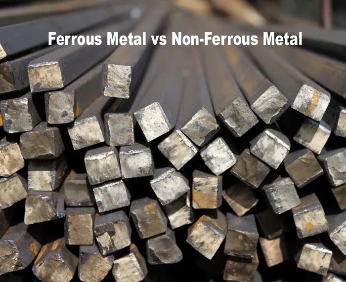
From Iron Alloys to Aluminum Alloys: Understanding the World of Ferrous and Non-Ferrous Metals
Delve into the world of metals with this comprehensive guide to ferrous and non-ferrous metals. Explore their properties, applications, and key differences.
-
Differences between Die Casting and Investment Casting
What does investment casting mean?Investment casting is also called lost wax casting or dewaxed casting. Making parts by investment casting is usually a more ti...
-
The benefits of sand mouldings in aluminium casting
The benefits of sand mouldings in aluminium castingSand casting is a very popular casting process, primarily because of the many benefits sand mouldings offer t...
